Workflow Inputs
When a process run is triggered manually or via a menu button, the process run can request additional inputs before running.
A manager requires a quote to be generated, but the payment due date for the quote needs to be a value decided as the quote is being generated. The manager could request a date input, so that once the process is triggered, a payment date can be entered by the user.
A manager wants to schedule a task such as "Manufacture X Erasers", and wants a specific task to be generated, depending on the quantity of erasers being manufactured. (i.e. A small-batch task vs a large-batch task).
Process inputs can be configured to support most field types within RAPID. These inputs can then be referenced within the process to alter it's flow and make process 'regard' its invoked context.
When a process is executing inputs are regarded the same whether they are started manually or from a Call Activity.
Adding Inputs to a Process Diagram
Inputs can be configured by:
- Select the Canvas background of a process diagram, to ensure no elements are selected.
You can tell whether an element is being configured, or the process diagram itself, by examining the object listed at the top of the Properties Panel. It should read: Process_X (Process).
- In the Properties Panel, click the Process Inputs chevron to expand it.
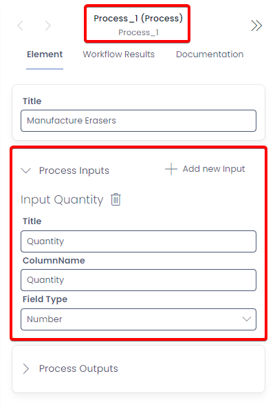
Each input that is added to this properties panel, will appear as a field that can have data entered once the process diagram is executed. Below is an explanation of what of the above configuration fields affects.
Configuring Call Activity Inputs
Adding an input to a diagram requires three pieces of information:
| Field | Explanation |
|---|---|
| Title | This is the user-friendly name that will appear above the field where the user can input data. |
| ColumnName | This is the internal variable name that Workflow will use to describe this field. These should be all lowercase, with no spaces. |
| Field Type | Here is where you set the expected input from the user. As this process diagram will accept a "Quantity of Erasers", it is set to anticipate the "Number" type of data. |
Types of Inputs
You can use the following field types as inputs:
| Type | Primitive | Additional Information |
|---|---|---|
| Single Line of Text | String | |
| String | ||
| Multiple Lines of Text | String | |
| Date and Time | Date | |
| Choice | String | These cannot be configured to present choices |
| Lookup | Integer | Can be configured to regard a list. Will be automatically populated when manually triggered from an item of the related type |
| Boolean | Boolean | |
| Number | Number | |
| Percentage | Number | |
| Currency | Number | Cannot configure the currency type |
| User | Integer | |
| JSON | String | |
| Whole number | Integer | |
| Globally Unique Identifier | String | |
| XML Data | String | |
| PowerBI Report | String |
Reading Inputs from a Process Diagram
In the example scenario above, we are manufacturing erasers and launching a different task depending on the quantity of erasers being created. Once our inputs are set up, we must configure elements on the page to read these input values.
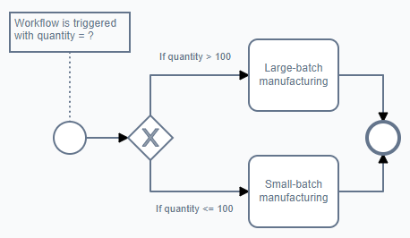
Above: A Gateway being configured to take the input value from the user, and selects a path depending on the value.
To configure this element, we select the Exclusive Gateway and add a Rule to its outputs. Here the following is configured:

| Field | Example | Explanation |
|---|---|---|
| Process Diagram | Process_1 | Which process diagram should this element read data from? This is useful if there is a sub-process or call activity occurring in a diagram. |
| Data Source | Process Inputs | This where the data is obtained from: Process Inputs. |
| ColumnName | Quantity | Which ColumnName input to read from. |
| Operand | > | The operand to apply to the value |
| Comparison | 100 | The value to compare with the ColumnName value. |
Now, if the quantity of erasers entered by the user during runtime is greater than 100, the Gateway will send the token through this output.
Manual Starts and Inputs
To enter inputs during a manual start:
-
Press the Launch button in the Workflow experience
-
A sidebar will open with the Process Inputs. Enter the values and press OK

- The workflow will trigger and produce a feedback diagram to display what occurred during the process run.
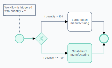
Above: The user entered "50" as the quantity of erasers in this example, so the gateway resolved this during the process run and sent the token down to the "Small-batch manufacturing" task.
Menu Button Starts and Inputs
When a menu button is configured to execute a workflow process, the following will occur:
- Find the item or table where the button is located and press it. In this example, the button is simply titled "Launch Process Run"
![]()
- A dialogue box will open, prompting the user to enter inputs

-
Press the OK button to trigger the process run's default start event
-
The workflow will trigger. The user can navigate to the process diagram to inspect the result of the process run.
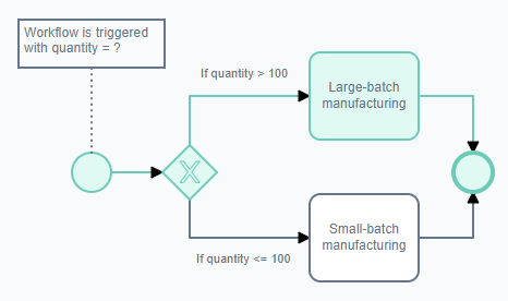
Above: The user entered "500" as the quantity of erasers in this example, so the gateway resolved this during the process run and sent the token up to the "Large-batch manufacturing" task.
Referencing inputs with an expression
Inputs are placed on an input's key within the process run. They can be referenced via:
<%= Process_1.inputs.{input column} %>